VMware Site Recovery Manager 8.x Upgrade Guide

This post will walk through an inplace upgrade of VMware Site Recovery Manager (SRM) to version 8.1, which introduces support for the vSphere HTML5 client and recovery / migration to VMware on AWS. Read more about what’s new in this blog post. The upgrade is relatively simple but we need to cross-check compatibility and perform validation tests after running the upgrade installer.

SRM81

Planning

  • The Site Recovery Manager upgrade retains configuration and information such as recovery plans and history but does not preserve any advanced settings
  • Protection groups and recovery plans also need to be in a valid state to be retained, any invalid configurations or not migrated
  • Check the upgrade path here, for Site Recovery Manager 8.1 we can upgrade from 6.1.2 and later
  • If vSphere Replication is in use then upgrade vSphere Replication first, following the steps outlined here
  • Site Recovery Manager 8.1 is compatible with vSphere 6.0 U3 onwards, and VMware Tools 10.1 and onwards, see the compatibility matrices page here for full details
  • Ensure the vCenter and Platform Services Controller are running and available
  • In Site Recovery Manager 8.1 the version number is decoupled from vSphere, however check that you do not need to perform an upgrade for compatibility
  • For other VMware products check the product interoperability site here
  • If you are unsure of the upgrade order for VMware components see the Order of Upgrading vSphere and Site Recovery Manager Components page here
  • Make a note of any advanced settings you may have configured under Sites > Site > Manage > Advanced Settings
  • Confirm you have Platform Services Controller details, the administrator@vsphere.local password, and the database details and password

Download the VMware Site Recovery Manager 8.1.0.4 self extracting installer here to the server, and if applicable; the updated Storage Replication Adapter (SRA) – for storage replication. Review the release notes here, and SRM upgrade documentation centre here.

Database Backup

Before starting the upgrade make sure you take a backup of the embedded vPostgres database, or the external database. Full instructions can be found here, in summary:

  • Log into the SRM Windows server and stop the VMware Site Recovery Manager service
  • From command prompt run the following commands, replacing the db_username and srm_backup_name parameters, and the install path and port if they were changed from the default settings
cd C:\Program Files\VMware\VMware vCenter Site Recovery Manager Embedded Database\bin
pg_dump -Fc --host 127.0.0.1 --port 5678 --username=db_username srm_db > srm_backup_name
  • If you need to restore the vPostgres database follow the instructions here

In addition to backing up the database check the health of the SRM servers and confirm there are no pending reboots. Log into the vSphere web client and navigate to the Site Recovery section, verify there are no pending cleanup operations or configuration issues, all recovery plans and protection groups should be in a Ready state.

Process

As identified above, vSphere Replication should be upgraded before Site Recovery Manager. In this instance we are using Nimble storage replication, so the Storage Replication Adapter (SRA) should be upgraded first. Download and run the installer for the SRA upgrade, in most cases it is a simple next, install, finish.


We can now commence the Site Recovery Manager upgrade, it is advisable to take a snapshot of the server and ensure backups are in place. On the SRM server run the executable downloaded earlier.

  • Select the installer language and click Ok, then Next
  • Click Next on the patent screen, accept the EULA and click Next again
  • Double-check you have performed all pre-requisite tasks and click Next
  • Enter the FQDN of the Platform Services Controller and the SSO admin password, click Next
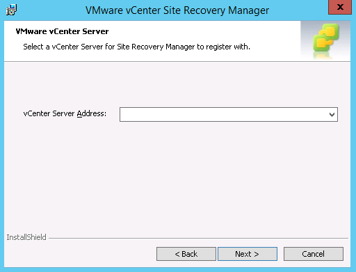
  • The vCenter Server address is auto-populated, click Next
  • The administrator email address and local host ports should again be auto-populated, click Next
  • Click Yes when prompted to overwrite registration
  • Select the appropriate certificate option, in this case keeping the existing certificate, click Next
  • Check the database details and enter the password for the database account, click Next
  • Configure the service account to run the SRM service, again this will be retain the existing settings by default, click Next
  • Click Install and Finish once complete


Post-Upgrade

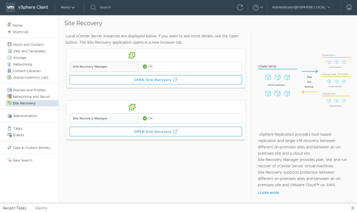
After Site Recovery Manager is upgraded log into the vSphere client. If the Site Recovery option does not appear immediately you may need to clear your browser cache, or restart the vSphere client service.

SRM_81

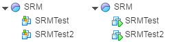
On the summary page confirm both sites are connected, you may need to reconfigure the site pair if you encounter connection problems.

SRM_81_1

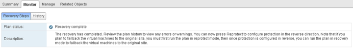
Validate the recovery plan and run a test to confirm there are no configuration errors.

SRM_81_2

The test should complete successfully.

SRM_81_5

I can also check the replication status and Storage Replication Adapter status.

SRM_81_4

Site Recovery Manager Configuration and Failover Guide

This post will walk through the configuration of Site Recovery Manager; we’ll protect some virtual machines with a Protection Group, and then fail over to the DR site using a Recovery Plan. The pre-requisites for this post are for Site Recovery Manager (SRM) and the Storage Replication Adapter (SRA) to be installed at both sites along with the corresponding vSphere infrastructure, and replication to be configured on the storage array. It is also possible to use vSphere Replication, for more information see the previous posts referenced below.

Part 1 – Nimble Storage Integration with SRM

Part 2 – Site Recovery Manager Install Guide

Part 3 – Site Recovery Manager Configuration and Failover Guide

Site Recovery Manager now has integration with the HTML5 vSphere client, see VMware Site Recovery Manager 8.x Upgrade Guide for more information.

Before creating a Recovery Plan ensure that you have read the documentation listed in the installation guide above and have the required components for each site. You should also make further design considerations around compute, storage, and network. In this post we will be using storage based replication and stretched VLANs to ensure resources are available at both sites. If you want to assign a different VLAN at the failover site then you can use SRM to reconfigure the network settings, see this section of the documentation center.

SRM

Configuring SRM

Log into the vSphere web client for the primary site as an administrator, and click the Site Recovery Manager icon.

config

The first step is to pair the sites together. When sites are paired either site can be configured as the protected site.

  • Click Sites, both installed sites should be listed, select the primary site.
  • On the Summary tab, in the Guide to configuring SRM box, click 1. Pair sites.
  • The Pair Site Recovery Manager Servers wizard will open. Enter the IP address or FQDN of the Platform Services Controller for the recovery site, and click Next.
  • The wizard then checks the referenced PSC for a registered SRM install. Select the corresponding vCenter Server from the list and enter SSO administrator credentials.
  • Click Finish to pair the sites together.

Now the sites are paired they should both show connected. When we configure protection one will be made the protected site and the other failover.

config3

Next we will configure mappings to determine which resources, folders, and networks will be used at both sites.

  • Locate the Guide to configuring SRM box and the subheading 2. Configure inventory mappings.
  • Click 2.1 Create resource mappings.
  • Expand the vCenter servers and select the resources, then click Add mappings and Next.
  • On the next page you can choose to add reverse mappings too, using the tick box if required.
  • Click Finish to add the resource mappings.

config4

  • Click 2.2 Create folder mappings.
  • Select whether you want the system to automatically create matching folders in the failover site for storing virtual machines, or if you want to manually choose which folders at the protected site map to which folders at the failover site. Click Next.
  • Select the folders to map for both sites, including reverse mappings if required, and click Finish.

config5

  • Click 2.3 Create network mappings.
  • Select whether you want the system to automatically create networks, or if you want to manually choose which networks at the protected site map to which networks at the failover site. Click Next.
  • Select the networks to map for both sites and click Next.
  • Review the test networks, these are isolated networks used for SRM test failovers. It is best to leave these as the default settings unless you have a specific isolated test network you want to use. Click Next.
  • Include any reverse mappings if required, then click Finish.

Next we will configure a placeholder datastore. SRM creates placeholder virtual machines at the DR site, when a failover is initiated the placeholder virtual machines are replaced with the live VMs. A small datastore is required at each site for the placeholder data, placeholder VMs are generally a couple of KBs in size.

  • Click 3. Configure placeholder datastore.
  • Select the datastore to be used for placeholder information and click Ok.

The screenshot below shows the placeholder VMs in the failover site on the left, and the live VMs in the protected site on the right.

placeholder

Although we followed the wizard on the site summary page for the above tasks, it is also possible to configure, or change the settings later, by selecting the site and then the Manage tab, all the different mappings are listed.

mappings

Site Protection

The following steps will configure site protection, we’ll start by adding the storage arrays.

  • Click 4. Add array manager and enable array pair.
  • Select whether to use a single array manager, or add a pair of arrays, depending on your environment, and click Next. I’m adding two separate arrays.

array1

  • Select the site pairing and click Next.
  • Select the installed Storage Replication Adapter and click Next.

array2

  • Enter the details for the two storage arrays where volumes are replicated and click Next.
  • Select the array pair to enable and click Next.
  • Confirm the details on the review page and click Finish.

An array pair can be managed by selecting the SRM site and clicking the Related Objects tab, then Array Based Replication. If you add new datastores to the datastore group, you can check they have appeared by selecting Array Based Replication from the Site Recovery Manager home page, select the array, and click the Manage tab. Array pairs and replicated datastores will be listed, click the blue sync icon to discover new devices.

Now the storage arrays are added we can create a Protection Group.

  • Click 5. Create a Protection Group.
  • Enter a name for the protection group and select the site pairing, click Next.

protection1

  • Select the direction of protection and the type of protection group. In this example I am using datastore groups provided by array based replication so I’ll need to select the array-pair configured above, and Next.

protection2

  • Select the datastore groups to protect, the datastores and virtual machines will be listed, click Next.
  • Review the configuration and click Finish.

The final step is to group our settings together in a Recovery Plan.

  • Click 6. Create a Recovery Plan.
  • Enter a name for the recovery plan and select the site pairing, click Next.
  • From the sites detected select the recovery site and click Next.
  • Select the Protection Group we created above and click Next.
  • Review the test networks, these are isolated networks used for SRM test failovers. It is best to leave these as the default settings unless you have a specific isolated test network you want to use. Click Next.
  • Review the configuration and click Finish.

Now we have green ticks against each item in the Guide to configuring SRM box, we can move on to testing site failover. The array based replication, Protection Groups, and Recovery Plans settings can all be changed, or new ones created, using the menus on the left handside of the Site Recovery Manager home page.

complete.PNG

Site Failover

SRM allows us to do a test failover, as well as an actual failover in the event of a planned or unplanned site outage. The test failover brings online the replicated volumes and starts up the virtual machines, using VMware Tools to confirm the OS is responding. It does not connect the network or impact the production VMs.

  • Log in to the vSphere web client for the vCenter Server located at the DR site.
  • Click Site Recovery, click Recovery Plans and select the appropriate recovery plan.
    • To test the failover plan click the green start button (Test Recovery Plan).
    • Once the test has completed click the cleanup icon (Cleanup Recovery Plan) to remove the test data, previous results can still be viewed under History.
  • To initiate an actual fail over click the white start button inside a red circle (Run Recovery Plan).
  • Select the tick-box to confirm you understand the virtual machines will be moved to different infrastructure.
  • Select the recovery type; if the primary site is available then use Planned migration, datastores will be synced before fail over. If the primary site is unavailable then use Disaster recovery, datastores will be brought online using the most recent replica on the storage array.
  • Click Next and then Finish.

failover

During the failover you will see the various tasks taking place in vSphere. Once complete the placeholder virtual machines in the DR site are replaced with the live virtual machines. The virtual machines are brought online in the priority specified when we created the Recovery Plan.

failover1

Ensure the virtual machines are protected again as soon as the primary site is available by following the re-protection steps below.

Site Re-Protection

When the primary site is available the virtual machines must be re-protected to allow failback. Likewise after failing back to the primary site the virtual machines must be re-protected to allow failover again to the DR site.

  • Log in to the vSphere web client for either site and click Site Recovery, Recovery Plans and select the appropriate Recovery Plan.
  • Under Monitor, Recovery Steps, the Plan status needs to show Recovery complete, before we can re-protect.

reprotect1

If the status shows incomplete then you can troubleshoot which virtual machine(s) are causing the problem under Related Objects, Virtual Machines. VMware Tools must be running on the VMs to detect the full recovery process.

  • To re-protect virtual machines click Reprotect from the Actions menu at the top of the page.
  • Click the tick-box to confirm you understand the machines will be protected based on the sites specified.

reprotect2

  • Click Next and Finish. The re-protect job will now run, follow the status in the Monitor tab.

reprotect3

Once complete the Plan Status, and Recovery Status, will show Complete. The virtual machine Protection Status will show Ok. The VMs are now protected and can be failed over to the recovery site. If you are failing back to the primary site follow the same steps as outlined in the SRM Failover section above. Remember to then re-protect the VMs so they can failover to the DR site again in the event of an outage. When a Protection Plan is active the status will show Ready, the plan is ready for test or recovery.

reprotect4

_______________

Part 1 – Nimble Storage Integration with SRM

Part 2 – Site Recovery Manager Install Guide

Part 3 – Site Recovery Manager Configuration and Failover Guide

Site Recovery Manager 6.x Install Guide

This post will walk through the installation of Site Recovery Manager (SRM) to protect virtual machines from site failure. SRM plugs into vCenter to protect virtual machines replicated to a failover site using array based replication or vSphere replication. In the event of a site outage, or outage of components within a site meaning production virtual machines can no longer run there; SRM brings online the replicated datastore and VMs in vSphere, with a whole bunch of automated customisation options such as assigning new IP addresses, boot orders, dependencies, running scripts, etc. After a failover SRM can reverse the replication direction and protect virtual machines ready to fail back, all from within the vSphere web client.

Site Recovery Manager now has integration with the HTML5 vSphere client, see VMware Site Recovery Manager 8.x Upgrade Guide for more information.

Requirements

  • SRM is installed on a Windows machine at the protected site and the recovery site. SRM requires an absolute minimum of 2vCPU, 2 GB RAM and 5 GB disk available, more is recommended for large environments and installations with an embedded database.
  • The Windows server should have User Access Control (UAC) disabled (in the registry, not just set to never notify) as this interferes with the install.
  • Each SRM installation requires its own database, this can be embedded for small deployments, or external for large deployments.
  • A vCenter Server must be in place at both the protected site and the recovery site.
  • SRM supports both embedded and external Platform Services Controller deployments. If the external deployment method is used ensure the vCenter at the failover site is able to connect to the Platform Services Controller (i.e. it isn’t in the primary site). For more information click here.
  • The vCenter Server, Platform Services Controller, and SRM versions must be the same on both sites.
  • You will need the credentials of the vCenter Server SSO administrator for both sites.
  • For vCenter Server 6.0 U2 compatibility use SRM v6.1.1, vCenter Server 6.0 U3 use SRM v6.1.2 and for vCenter Server 6.5 and 6.5 U1 use v6.5 or v6.5.1 of SRM.
  • Check compatibility of other VMware products using the Product Interoperability Matrix.
  • If there any firewalls between the management components review the ports required for SRM in this KB.
  • SRM can be licensed in packs of 25 virtual machines, or for unlimited virtual machines on a per CPU basis with vCloud Suite. Read more about SRM licensing here.
  • Array based replication or vSphere Replication should be in place before beginning the SRM install. If you are using array based replication contact your storage vendor for best practices guide and the Storage Replication Adapter which is installed on the same server as SRM.

As well as the requirements listed above the following points are best practices which should also be taken into consideration:

  • Small environments can host the SRM installation on the same server as vCenter Server, for large environments SRM should be installed on a different system.
  • For vCenter Server, Platform Services Controller, Site Recovery Manager servers, and vSphere Replication (if applicable) use FQDN where possible rather than IP addresses.
  • Time synchronization should be in place across all management nodes and ESXi hosts.
  • It is best practice to have Active Directory and DNS servers already running at the failover site.

Installation

In this example we will be installing Site Recovery Manager using Nimble array based replication. There is a vCenter Server with embedded Platform Services Controller already installed at each site. The initial screenshots are from an SRM v6.1.1 install, but I have also validated the process with SRM v6.5.1 and vCenter 6.5 U1.

SRM

The virtual machines we want to protect are in datastores replicated by the Nimble array. For more information on the storage array pre-installation steps see the Nimble Storage Integration post referenced below. The Site Recovery Manager install, configuration, and failover guides have no further references to Nimble and are the same for all vendors and replication types.

Part 1 – Nimble Storage Integration with SRM

Part 2 – Site Recovery Manager Install Guide

Part 3 – Site Recovery Manager Configuration and Failover Guide

Installing SRM

The installation is pretty straight forward, download the SRM installer and follow the steps below for each site. We’ll install SRM on the Windows server for the primary / protected site first, and repeat the process for the DR / failover site. We can then pair the two sites together and create recovery plans.

SRM 6.5.1 (vSphere 6.5 U1) Download | Release Notes | Documentation

SRM 6.5 (vSphere 6.5) Download | Release Notes | Documentation

SRM 6.1.2 (vSphere 6.0 U3) Download | Release Notes | Documentation

SRM 6.1.1 (vSphere 6.0 U2) Download | Release Notes | Documentation

Log into the Windows server where SRM will be installed as an administrator, and right click the downloaded VMware-srm-version.exe file. Select Run as aministrator. If you are planning on using an external database then the ODBC data source must be configured, for SQL integrated Windows authentication make sure you log into the Windows server using the account that has database permissions to configure the ODBC data source, and run the SRM installer.

Select the installer language and click Ok.

SRM1

Click Next to begin the install wizard.

SRM2

Review the patent information and click Next.

SRM3

Accept the EULA and click Next.

SRM4

Confirm you have read the prerequisites located at http://pubs.vmware.com/srm-61/index.jsp by clicking Next.

SRM5

Select the destination drive and folder, then click Next.

SRM6

Enter the IP address or FQDN of the Platform Services Controller that will be registered with this SRM instance, in this case the primary site. If possible use the FQDN to make IP address changes easier if required at a later date. Enter valid credentials to connect to the PSC and click Next. If your vCenter Server is using an embedded deployment model then enter your vCenter Server information.

SRM7

Accept the PSC certificate when prompted. The vCenter Server will be detected from the PSC information provided. Confirm this is correct and click Next. Accept the vCenter certificate when prompted.

SRM8

Enter the site name that will appear in the Site Recovery Manager interface, and the SRM administrator email address. Enter the IP address or FQDN of the local server, again use the FQDN if possible, and click Next.

SRM11

In this case as we are using a single protected site and recovery site we will use the Default Site Recovery Manager Plug-in Identifier. For environments with multiple protected sites create a custom identifier. Click Next.

SRM12

Select Automatically generate a certificate, or upload one of your own if required, and click Next.

SRM13

Select an embedded or external database server and click Next. If you are using an external database you will need a DSN entry configured in ODBC data sources on the local Windows server referencing the external data source. Click Next.

SRM14

If you opted for the embedded database you will be prompted to enter a new database name and create new database credentials. Click Next.

SRM15

Configure the account to run the SRM services, if applicable, and click Next.

SRM10

Click Install to begin the installation.

SRM9

Site Recovery Manager is now installed. Repeat the process to install SRM on the Windows server in the DR / recovery site, referencing the local PSC and changing the site names as appropriate. If you are using storage based replication you also need to install the Storage Replication Adapter (SRA) on the same server as Site Recovery Manager. In this example I have installed the Nimble SRA, available from InfoSight downloads, which is just a next and finish installer.

After each site installation of SRM you will see the Site Recovery Manager icon appear in the vSphere web client for the corresponding vCenter Server.

SRMvsphereSRMvsphere2

Providing the datastores are replicated, either using vSphere replication or array based replication, we can now move on to pairing the sites and creating recovery plans in Part 3.

_______________

Part 1 – Nimble Storage Integration with SRM

Part 2 – Site Recovery Manager Install Guide

Part 3 – Site Recovery Manager Configuration and Failover Guide