The VNXe is the most affordable hybrid and all-flash array across the EMC product range. Although the future potentially sits with the newly released Unity line, the VNXe remains a popular, flexible, and efficient storage solution for SMBs and ROBOs. This post will walk through the setup of an EMC VNXe device.

Architecture
The VNXe 3200 is powered by dual Intel Xeon E5-2407 4-Core processors, providing up to 3x the performance of its 3150 predecessor. The Disk Processor Enclosure (DPE) leverages dual controllers and 6-Gb SAS back-end connectivity to deliver high levels of availability and efficiency, whilst lowering storage costs per I/O. Disk Array Enclosures (DAE) are added to scale out capacity up to 500 TB top end. There is concurrent support for NAS and SAN, with CIFS, SMB3, NFS, iSCSI and Fibre Channel (up to 8Gb) protocols, whilst the unit itself has a small datacentre footprint. For more information see the EMC VNXe Data Sheet.
Some considerations when creating storage pools; typically we want to configure less storage pools to reduce complexity and increase flexibility, however configuring multiple storage pools may be required if you want to separate workloads. Storage pools must maintain free capacity to operate, EMC recommend at least 10%. You will need to make design decisions based on your environment around storage pool capacities and configured RAID protection. The VNXe range offers multicore RAID 1/10/5/6 configured at storage pool level. EMC generally recommends smaller RAID widths as providing the best performance and availability, at the cost of slightly less usable capacity, e.g. for RAID 6 use 4+2 or 6+2 instead of 10+2 or 14+2.
VNXe arrays use the first 4 drives to store configuration information and critical system data, these are known as the system or vault drives and run from DPE Disk 0 through to DPE Disk 3. The system drives can be added to storage pools however usable capacity of system drives is reduced, therefore storage pools utilising system drives should use a smaller RAID width. For larger configurations with high drive counts EMC does not recommend using the system drives as heavy client workload may slow down management operations (does not apply to all-flash).
Requirements
In addition to the boxed system components you will need:
- Cabinet vertical space of 2U for the DPE, and 2U for each optional 25-drive DAE.
- 2 x Cat 5e or better GbE management connections.
- Between 2 and 8 Cat 5e or better GbE or 10GbE data connections, or, between 2 and 8 Gb FC connections, depending on your chosen connection protocol.
- A Windows based computer to run the initialisation and setup.
- If you are unable to connect the Windows computer to the same subnet as the EMC VNXe then you will need a USB drive to configure the array with a management IP address.
- Phillips screwdriver for installation.
Unboxing
The VNXe base comes with the following:
- Disk Processor Enclosure (DPE) 2U component consisting of 12 x 3.5″ bays or 25 x 2.5″ bays.
- Rail kit consisting of 2 adjustable rails and 10 screws, or 2 snap-in rails and 6 screws.
- Accessory kit consisting of an mini-USB adaptor, cable ties, stickers, etc.
- Front bezel for DPE.
- Power cords.
Any additional disk shelves contain:
- Disk Array Enclosure (DAE) 2U component consisting of 12 x 3.5″ bays or 25 x 2.5″ bays.
- Rail kit consisting of 2 adjustable rails and 10 screws, or 2 snap-in rails and 6 screws.
- Front bezel for DAE.
- Power cords.
- Mini-SAS and mini-SAS HD to mini-SAS cables.
Racking
EMC recommend installing the DPE at the bottom of the cabinet and installing any additional DAE’s above. The snap-in method is the most commonly used rail set and the one we will use here. For assistance with racking the adjustable rails see page 16 of the EMC VNXe Install Guide.
Locate the left and right markings on each rail. Align the 2U key tabs with the U-space in the rear rack channel. Push the key tabs and adaptors into the rear mounting holes until the spring clips snap into place. Round the front push in the spring clip and release once the rail is lined up with the mounting holes. Secure the rear of the rail using 1 x M5 screw on each side.
Slide the DPE into the rails until they click into the rear tabs on each rail. The tabs secure and support the rear of the enclosure, the front is secured using 2 x M5 screws on each side. Repeat the process for any additional DAEs.

Cabling
First connect the 2 management ports to the switch, management ports have a LAN/management symbol above them. Do not use the service ports, service ports have a wrench/spanner symbol above them. Next plug in the cables for your chosen front end connectivity, i.e. Fibre Channel or Ethernet. Front end ports need to be connected and configured symmetrically across both storage processors to facilitate high availability. Furthermore you should use all front-end ports that are installed in the system, so that workload is spread across as many resources as possible. NAS ports should also be configured with LACP grouped per storage processor, to provide path redundancy and performance improvements.
If you have purchased additional DAEs then these need to be connected using the included SAS cables. There are 2 on-board 6Gb SAS ports in each storage processor in the DPE. When cabling DAEs to the DPE, balance them as evenly as possible across all available buses. The drives in the DPE are serviced by SAS Bus 0; therefore, the first DAE should be cabled to SAS Bus 1. Connect SP A SAS Port 1 to DAE 1 Link Controller Card (LCC) A (cable 1 in the image below). Connect SP B SAS Port 1 to DAE 1 LCC B (cable 2).

The mini-SAS HD connectors are used for the DPE ports, the mini-SAS connectors are used for DAE ports. Mini-SAS to mini-SAS cables are used for cabling DAEs together. If you are attaching additional DAE’s see page 28 of the EMC VNXe Install Guide.
The power cables included with the array are colour coded with an intended use of: grey for Power Distribution Unit (PDU) A, black for PDU B. Once the array has power it will take approximately 10 – 15 minutes to power up. Finally, clip the front bezels into place and secure with the key included.

Setup
To access the web UI for setup we have a couple of options for automatic or manual IP addressing.
Automatic – if the array has access to network DHCP and DNS servers (with dynamic DNS enabled) then it will automatically be assigned an IP address. After power up if the SP Fault LED is solid blue then a management address has been assigned. This IP is dynamically added to DNS in the format of serialnumber.domain. If the SP Fault LED alternates between solid blue and flashing amber then a management address has not been assigned as the DHCP or DNS server could not be reached.
Manual – download and install the Connection Utility from EMC Downloads. The Connection Utility gives you two options; automatically detect unconfigured storage systems in the same subnet as your Windows client, or manually configure an IP in a configuration file for use with a USB flash drive which the array automatically reads.
Depending on how IP addressing has been assigned open a browser and enter the IP address manually configured, or the DNS entry (serialnumber.dnszone). Log in to Unisphere using the default credentials admin Password123#.

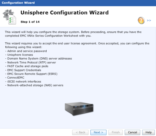
The Initial Configuration Wizard launches the first time you login. This self explanatory wizard guides you through the basic setup of the array, any settings you skip here can be configured later through the appropriate menus.
Once the configuration wizard is complete you will be returned to the home dashboard. It is recommended that the operating system is updated straight away. This can be achieved from the Settings drop down menu, and selecting Update software. Software can either be obtained online direct from the VNXe, or downloaded from EMC Downloads and then uploaded to the array. If you skipped the configuration wizard there are some basic configuration settings below to get you started.
First browse to the Management Settings page of the Settings drop down menu. Under the General tab we can configure the system name and management network settings. The Network tab features DNS settings, NTP settings, and remote logging.

To apply a license (.lic file provided by EMC) go to Settings, Manage Licenses; upload and install the license file. Also under Settings select Configure alerts, connect to EMC and configure SMTP and alert settings here.

It is recommended that physical network interfaces are pooled together. To configure link aggregation browse to Settings, More Configuration, Advanced Configuration. Tick the Aggregation box.

Storage pools are configured under System, Storage Pools. You will see 2 default pools; Hot Spare Pool and Unconfigured Disks. To configure the number of hot spares, or configure a storage pool and RAID group, select the appropriate pool and click Configure Disks. Follow the Disk Configuration Wizard.

To change the admin password at any time go to Settings, User administration. To enable SSH (optional) navigate to Settings, Service System and enter the service password. Select Enable SSH and click Execute service action.
You can now move on to configure the chosen protocol for the array, whether that be creating CIFS/NFS servers and shares through Settings, Manage Shared Folder Server Settings, or presenting iSCSI or FC storage through Hosts or Settings, iSCSI Server Settings. For further assistance with the VNXe GUI see EMC Unisphere for VNXe.

Loovely blog you have here
LikeLike